

Channel Simulator
The ChannelSimulator lets you run the full communication and multi-channel sensing pipeline with no radio attached. It replaces the USRP with shared-memory “air” and builds a scatterer-based multipath channel: the transmitted samples pass through a LoS path, optional static multipath paths, and moving scatterers with delay / Doppler / gain / array response. A fixed integer timing offset can be folded into each path delay; the communication/bistatic receive chain can also apply a UE sample-clock offset, then relative carrier frequency offset (CFO), and AWGN is added to every RX output. The timing offset is a fixed integer sample offset, while sample_rate_offset_ppm models sampling frequency offset (SFO) between the BS and UE sample clocks.
Each sensing RX channel is treated as one antenna. The array response can be generated from a parametric uniform linear array (ULA, array_spacing_lambda) or loaded as a custom array manifold matrix from steering_override_file. The communication channel is a realistic multipath channel: a LoS path plus scatterer returns, so the UE’s bistatic sensing can also detect range-Doppler targets.
How it works
Section titled “How it works”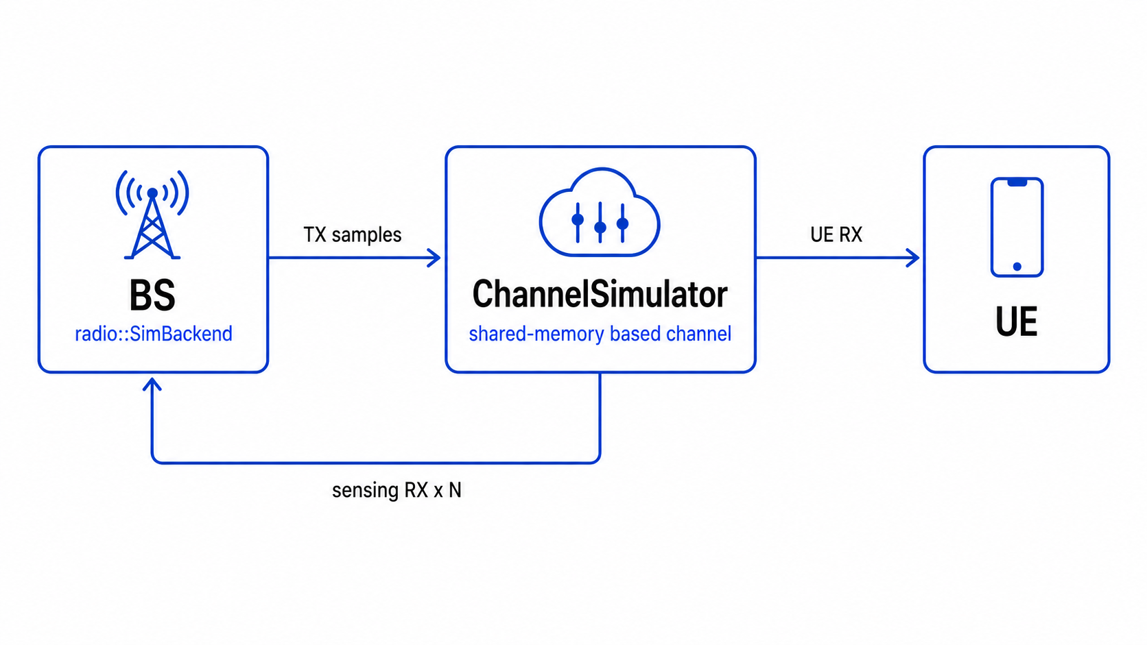
All three processes attach to POSIX shared-memory rings named by simulation.session. The engines select the backend with radio_backend: sim in their YAML. The radio::SimBackend implements the same OpenISAC radio HAL used by the UHD backend, so the BS/UE/sensing hot paths drive radio::ITxStream / radio::IRxStream interfaces regardless of whether the underlying transport is shared memory or a USRP. radio_backend: uhd (the default) keeps the hardware behaviour.
The shared-memory streams use one absolute sample timeline. The simulated device clock runs before the first sample is transmitted, timed TX metadata places the first burst sample on that clock, and timed RX commands seek to the requested absolute sample. The BS uplink RX timeline continues through silence before the UE starts transmitting instead of beginning at an unrelated ring-local zero. Consequently, UE downlink RX alignment and uplink TX window movement retain the same clock relationship as timed USRP streams. Changing sync_tracking.desired_peak_pos changes the local delay/TO_UE reference coordinate, but an eRTM-corrected physical delay peak remains at the same position.
cd build && cmake .. && make -j ChannelSimulator BS UERun the three processes on the same machine in three terminals:
cd buildcp ../config/BS_Sim.yaml BS.yamlcp ../config/UE_Sim.yaml UE.yaml
# 1) start the "air" FIRST (it creates the shared memory and is the sample clock)./ChannelSimulator                 # reads BS.yaml (+ its simulation: block)
# 2) start the transmitter / monostatic sensing./BS
# 3) start the receiver / comm demod./UE
eRTM simulation preset
Section titled “eRTM simulation preset”Use the dedicated pair when validating bidirectional timing and absolute eRTM delay correction:
cd buildcp ../config/BS_Sim_eRTM.yaml BS.yamlcp ../config/UE_Sim_eRTM.yaml UE.yaml
./ChannelSimulator  # terminal 1./BS                # terminal 2./UE                # terminal 3
# Optional: inspect the uplink/downlink spectra and eRTM correlation result.python3 ../scripts/plot_ertm_debug.py
This preset enables the duplex simulator, the maximum_likelihood timing metric, eRTM debug output, and ertm_absolute bistatic delay correction. It disables BS monostatic sensing RX, CFO, SRO, and UE predictive-delay tracking so the first run isolates eRTM timing behavior. Both files use the dedicated oisac_ertm_sim session and must be copied as a pair.
Start ChannelSimulator first. By default the hub paces output to wall-clock sample time and still uses shared-memory backpressure: if communication RX or sensing RX is enabled but the corresponding consumer process is not reading from shared memory, the related ring buffer will fill and the whole simulation will wait. Start every enabled receiver; if you only need one side, disable the unused output in the simulation: block:
- Sensing only: set
enable_comm_rx: false; the hub does not produce communication RX output, so run onlyChannelSimulator+BSand skipUE. - Comm only: set
enable_sensing_rx: false; the hub does not produce sensing RX output, but still runChannelSimulator+BS+UEbecause the BS transmits and the UE receives the communication stream.
There are two ways to disable sensing RX: set enable_sensing_rx: false, or set sensing_rx_channel_count: 0.
To view monostatic sensing results, run python3 scripts/plot_sensing_fast.py. As in hardware mode, RD streaming starts when the viewer connects.
Configuration
Section titled “Configuration”Configure the channel in the simulation: block in BS_Sim.yaml:
radio_backend: simsimulation: session: oisac_sim # must match across all three processes enable_comm_rx: true # produce the comm RX path (false = sensing-only, no UE) enable_sensing_rx: true # produce the sensing RX paths (false = comm-only) enable_uplink: false # route UE ul.tx to BS rx.ul; true in BS_Sim_Duplex.yaml pacing_enabled: true # pace shared-memory output to wall-clock sample time noise_power_dbfs: -50 # AWGN per RX channel; <= -200 disables cfo_hz: 0.0 # initial BS->UE CFO; UE->BS is opposite/scaled and follows TX retune sample_rate_offset_ppm: 0.0 # UE sample clock offset relative to the BS clock timing_offset_samples: 0 # fixed integer sample offset, folded into path delays array_spacing_m: 0.04283 # physical ULA spacing (m); d/lambda scales with center_freq # (42.83 mm = lambda/2 @ 3.5 GHz, matches the sensing viewers). # Set <= 0 to fall back to the legacy array_spacing_lambda. array_spacing_lambda: 0.5 # legacy fixed spacing (wavelengths); used only if array_spacing_m <= 0 ring_capacity_samples: 262144 # about 2 frames; small keeps TX close to the hub steering_override_file: "" # array manifold: [num_targets x num_channels] complex<float>, row-major; empty = ULA comm_multipath_taps: # communication LoS path + static multipath paths - { delay_samples: 0, gain_db: 0, phase_deg: 0 } targets: # monostatic sensing scatterers (with array response) - { range_m: 30, velocity_mps: 5, gain_db: -6, angle_deg: 20 } - { range_m: 75, velocity_mps: -3, gain_db: -12, angle_deg: -10 } # bistatic_targets: # optional independent scene for the bistatic (comm) channel # - { range_m: 45, velocity_mps: 8, gain_db: -8, angle_deg: 0 }The number of sensing antennas equals the number of sensing_rx_channels entries.
sample_rate_offset_ppm models one endpoint-level sampling clock error: the UE sample rate is BS_rate * (1 + ppm * 1e-6). BS TX, BS uplink RX, and all BS sensing RX channels stay on the same BS sample clock; UE downlink RX and UE uplink TX stay on the same UE sample clock. The simulator therefore resamples the BS->UE communication path by that ratio and the UE->BS uplink path by its reciprocal, while monostatic BS sensing channels are not resampled.
targets describes the scatterer scene seen by monostatic sensing and generates the corresponding array response for each sensing antenna. The bistatic (communication) channel can be configured separately with bistatic_targets; if it is omitted, the simulator reuses targets, so the same scatterer scene drives both the monostatic and bistatic chains. Because the communication RX is single-antenna, angle_deg is not used in the bistatic channel calculation. To override the array manifold, provide num_targets x num_channels little-endian complex<float> values in row-major order via steering_override_file; each row corresponds to one target. Once a custom array-manifold matrix is configured, targets[].angle_deg no longer participates in the monostatic array-response calculation. Compute the angle-dependent amplitude and phase for every antenna element in advance and store those values in the matrix.
When simulation.enable_uplink is enabled, the UE->BS simulated uplink uses the same communication-channel scene as the BS->UE downlink. In that scene, the static multipath components configured by comm_multipath_taps and the selected bistatic-scatterer components are both superimposed on the direct path; the bistatic scatterers come from bistatic_targets when configured, or fall back to targets otherwise.
Channel model
Section titled “Channel model”The model is applied to transmitted samples in this order.
- For each scatterer, compute integer propagation delay, Doppler, and complex gain; the monostatic sensing path also applies the array manifold vector.
- The communication/bistatic path first adds the LoS path and static multipath paths, then adds the scatterer-return components.
- The BS->UE communication path is resampled by
1 + sample_rate_offset_ppm * 1e-6; when uplink simulation is enabled, the UE->BS path is resampled by the reciprocal ratio. - The communication/bistatic path applies relative CFO to the whole received signal: BS->UE uses
cfo_hz, while UE->BS uses its negative; the monostatic sensing path does not apply CFO. - AWGN is added to every RX output.
Target round-trip delay, sample delay, and Doppler are:
Here is range_m, is velocity_mps, is the BS sample_rate, is center_freq, and is timing_offset_samples. The term is a fixed integer sample offset; SFO is modeled separately by the communication-path resampler.
The ULA array manifold is:
where is the antenna index. The normalized element spacing is:
where is array_spacing_m and is the normalized element spacing in wavelengths. It is derived from the physical spacing and carrier frequency, so the recovered angle remains correct at any center_freq; the viewers invert the phase slope using the same physical spacing. With array_spacing_m <= 0, the frequency-independent legacy parameter array_spacing_lambda is used instead. If steering_override_file is set, the simulator reads directly from the array-manifold matrix instead of generating it from angle_deg. The custom matrix must therefore already encode the target angle’s amplitude and phase response at every antenna element.
For monostatic sensing RX antenna :
The monostatic sensing channel shares the simulator clock with the transmitter and does not apply relative CFO or UE sample-clock offset. In the equation above, is AWGN.
The communication/bistatic RX is single-antenna. The LoS/static multipath paths first form the communication multipath component:
Here comes from comm_multipath_taps[].delay_samples, and is determined by gain_db and phase_deg. Scatterer-return components are added to the same communication channel:
With SFO disabled, the communication/bistatic chain then applies relative CFO and AWGN. The same BS/UE oscillator mismatch has the opposite sign on the reciprocal link:
When UE downlink tracking produces an RX frequency correction, the simulation backend now retunes the uplink TX just like the real-USRP path. Let ( in TDD). The two residual CFOs are
In TDD, ; in FDD, the uplink TX correction is scaled by the carrier ratio . The shared control block carries the logical TX target-carrier correction rather than UHD’s API-specific TX dsp_freq sign.
With sample_rate_offset_ppm enabled, the simulator first forms on the source clock and passes it through a 32-tap, 1024-phase Kaiser-windowed sinc polyphase resampler. Positive ppm means the UE clock is faster than the BS clock, so BS->UE communication produces samples at . The downlink CFO phasor step uses that UE-side sample rate. After the reciprocal resampler returns UE->BS uplink output to the BS clock, the simulator applies the current residual CFO at the BS-side sample rate without resetting the continuous phase when the frequency step changes.
By default, targets drives both the monostatic sensing antennas (with array manifold) and the bistatic communication channel (single-antenna, no array manifold), modelling one coherent scene. Set bistatic_targets to give the bistatic/communication channel its own independent scatterers. comm_multipath_taps configures the delay, gain, and initial phase of the LoS path and static multipath paths. The UE->BS uplink reuses this same communication-channel model so the simulated TDD uplink is reciprocal with the downlink channel shape.
Notes and limits
Section titled “Notes and limits”- Each process stops cleanly on Ctrl-C (SIGINT), independently of the others; the hub unlinks its shared memory on exit.
- The hub is paced by default: each processed BS-clock chunk is released after
chunk_samples / sample_ratewall-clock time. Setsimulation.pacing_enabled: falsefor fastest-possible batch simulation. - Keep
ring_capacity_samplessmall, around a couple of frames, so the transmitter cannot race far ahead of the hub and overflow the monostatic TX/RX pairing queue. sample_rate_offset_ppmmodels one endpoint-level UE/BS SFO.timing_offset_samplesremains only a fixed integer sample offset and does not drift over time.- Timed simulated streams share an absolute sample clock. The clock remains at zero before the first TX, so a UE started before the BS still selects the same initial timed start. After the first TX establishes the origin, time advances only with processed air samples and is independent of whether the simulation keeps up with wall time. An RX request before the actual TX origin is aligned to that origin.
- With
sync_tracking.predictive_delay: true, the UE checks whether the shared-oscillator ppm implied bycfo_hz / center_freqmatchessample_rate_offset_ppm. The simulator permits CFO and SRO to be configured independently, so it warns on a mismatch; disable predictive delay when the mismatch is intentional to avoid interpreting CFO as sample-clock drift. - The simulator does not model fractional delay; all propagation delays and configured timing offsets are quantized to integer samples.